
Initializing Discrete-Time Components
A discrete-time component computes each sample from earlier samples, so before the first tick it needs values for those earlier samples, provided as initial conditions. This page covers how to supply them, and the convention the DiscreteComponents library uses to let a user of a component choose how it starts up.
See Discrete-Time Modeling for clocks and the shift operators, and Clocks for the syntax reference.
Initial conditions refer to the past
The initial condition of a clocked variable is given with initial and a past clock reference:
initial x@(clk-1) = 1.0The shift is there because the update performed at the first tick, x@clk instead would fix the result of the first update rather than the state it starts from.
One initial equation is needed for every shift depth the component reads. A component that uses x@(clk-2) needs both:
initial x@(clk-1) = 0.0
initial x@(clk-2) = 0.0
When the depth is itself a parameter, generate the equations with a loop. This is how NDelay fills its delay line:
component NDelay@[input clk extends Discrete]
  u = RealInput@[clk]() {^u}
  y = RealOutput@[clk]() {^y}
  structural parameter n::Integer
  parameter initial_condition::Real = 0
relations
  y = u@(clk-n)
  for i in 1:n
    initial u@(clk-i) = initial_condition
  end
end
To set the initial condition of a subcomponent's variable from a parent, write the equation in the parent's relations block — for example initial secondorder.x = 0.0.
The InitialCondition enum
An initial x@(clk-1) = … equation fixes the internal state of the component. A user of the component typically specifies the intended start-up behavior instead, for example "start with the output at 5.0" or "start in steady state". The DiscreteComponents.InitialCondition enum expresses this specification:
| Variant | Meaning |
|---|---|
InitialOutput(y0) | The first emitted output should equal y0. |
InitialState(x0) | The internal state starts at x0. |
SteadyState | Start in equilibrium for the current input, so the output does not jump at |
InitialOutputArray(y0) | InitialOutput for a vector-valued output. |
InitialStateArray(x0) | InitialState for a state vector. |
Not every variant is applicable to every component, and each component documents which ones it accepts. The array variants are usually accepted only by components with array state; FIRFilter is a scalar component that also accepts InitialStateArray(x0), which specifies an input history that is not constant.
Passing one when instantiating a component looks like this:
filt = DiscreteComponents.ExponentialFilter(a = 0.2,
         initialization = DiscreteComponents.InitialCondition.InitialOutput(y0 = -1))
The Sliding-Mode Control example uses exactly this to start its filter and its derivative block at known values.
Implementing the enum in your own component
The component declares a structural parameter of the enum type and switches on it in relations. Each case supplies whatever initial equations that mode implies. (See Enums and switch-case for the general construct.)
Here is ExponentialFilter, which is the smallest complete illustration:
component ExponentialFilter@[input clk extends Discrete]
  u = RealInput@[clk]() {^u}
  y = RealOutput@[clk]() {^y}
  parameter a::Real = 0.1
  structural parameter initialization::InitialCondition = DiscreteComponents.InitialCondition.InitialOutput(y0=0.0)
relations
  y@clk = (1 - a) * y@(clk-1) + a * u@clk

  switch initialization
  case InitialOutput
    initial y@(clk-1) = (initialization.y0 - a*u@clk) / (1 - a)
  case SteadyState
    initial y@(clk-1) = u@clk
  case InitialState
    initial y@(clk-1) = initialization.x0
  end
end
Three patterns matter here. The first is visible in the listing above; the other two are shown with the components that need them.
Solve backwards through the update equation
The InitialOutput case is not initial y@(clk-1) = initialization.y0. The value being set is the state before the first update, and the first update will transform it. To make the first emitted sample equal y0, invert the update equation. For the filter,
which is exactly the expression in the listing. The direct assignment initial y@(clk-1) = initialization.y0 would instead produce a first output that differs from y0 by one filter update.
InitialState, by contrast, does assign directly — that is what distinguishes the two modes.
Reject the modes you do not support
Some modes are not applicable to some components — a pure integrator has no steady state for a non-zero input, and most scalar blocks cannot use an array variant. Put error(...) on the right-hand side of the initial equation for those cases, so that the user receives an explicit error message instead of a numerical result that is difficult to interpret:
  switch initialization
  case InitialOutput
    initial x@(clk-1) = initialization.y0
  case InitialState
    initial x@(clk-1) = initialization.x0
  case SteadyState
    initial x@(clk-1) = error("SteadyState is not supported for this component; use InitialOutput or InitialState")
  end
The discrete-time PID controllers DiscretePIDStandard and DiscretePIDParallel follow both patterns. InitialOutput(y0) back-solves the integrator state so that the first unsaturated control signal equals y0, which provides bumpless transfer from an actuator that is already held at y0. SteadyState is rejected with an error when with_I = true, because an integrator has no unique steady state. The default is InitialState(x0 = 0.0), which sets the integrator state directly.
Switches can nest
When a component has two structural choices that interact, nest the switches. The DiscreteIntegrator picks a discretization method and an initialization mode, and the back-solved expression differs per method — forward Euler reads u@(clk-1) while backward Euler reads u@clk, so the correction term is not the same:
  switch method
  case Forward
    initial u@(clk-1) = 0
    x@clk = x@(clk-1) + k * Ts * u@(clk-1)
    switch initialization
    case InitialOutput
      initial x@(clk-1) = initialization.y0
    ...
    end
  case Backward
    x@clk = x@(clk-1) + k * Ts * u@clk
    switch initialization
    case InitialOutput
      initial x@(clk-1) = initialization.y0 - k*Ts*u@clk
    ...
    end
  end
A worked example
Below, three exponential filters see the same constant input of 1.0 but start differently: one with its first output forced to 2.0, one with its internal state set to -1.0, and one in steady state. All three converge to the input; only their transients differ. Download as a Dyad projectdiscreteinit.zipOpen in Dyad Studio
"""
Three identically-parameterized exponential filters started three different ways,
to show what each `InitialCondition` variant does to the first samples.
"""
test component InitializationDemo
  source = BlockComponents.Sources.Constant(k = 1.0)
  sampler = DiscreteComponents.Sampler()
  clock = DiscreteComponents.PeriodicClock(dt = 0.1)
  "First output prescribed by InitialOutput"
  filt_out = DiscreteComponents.ExponentialFilter(a = 0.2,
      initialization = DiscreteComponents.InitialCondition.InitialOutput(y0 = 2.0))
  "Internal state prescribed by InitialState"
  filt_state = DiscreteComponents.ExponentialFilter(a = 0.2,
      initialization = DiscreteComponents.InitialCondition.InitialState(x0 = -1.0))
  "Started in equilibrium with the input"
  filt_ss = DiscreteComponents.ExponentialFilter(a = 0.2,
      initialization = DiscreteComponents.InitialCondition.SteadyState())
relations
  connect(source.y, sampler.u)
  connect(sampler.y, clock.y, filt_out.u, filt_state.u, filt_ss.u)
end

analysis InitializationDemoAnalysis
  extends TransientAnalysis(stop = 2.0)
  model = InitializationDemo()
endusing Plots
using DyadInterface
result = InitializationDemoAnalysis()
model = artifacts(result, :SimplifiedSystem)
p1 = plot(result; idxs = model.filt_out.y, title = "InitialOutput(y0 = 2.0)")
p2 = plot(result; idxs = model.filt_state.y, title = "InitialState(x0 = -1.0)")
p3 = plot(result; idxs = model.filt_ss.y, title = "SteadyState")
plot(p1, p2, p3; layout = (3, 1), legend = false, xlabel = "t", ylabel = "y",
size = (600, 550), plot_title = "Same filter, three initializations")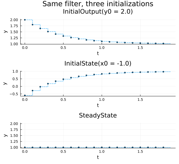
The SteadyState panel is flat at the input value: the filter starts already in equilibrium, so it never moves. The InitialOutput panel begins at exactly 2.0 — this is the property that the back-solved initial state guarantees — and decays towards the input from above. The InitialState panel starts at -0.6, not at -1.0: setting the stored state means the first output is already one filter step away from it,
Limitations
The state is not inferred from a requested output. Writing
y@clk = y0does not causey@(clk-1)to be back-solved. The component author has to do the inversion, which is why theInitialOutputcases above look the way they do. This limitation exists due to the lack of a general nonlinear solver for initialization of discrete-time partitions (which in general would have an unbounded execution time).Only explicit
initialequations are supported. Aninitialmodifier on a clocked variable, such asvariable x::Real(initial = 1.0), does not supply the value ofx@(clk-1); the compiler then reports that an initialization equation is required for the shifted variable. Use aninitialequation instead.
See also
Discrete-Time Modeling — clocks, shift operators and partitions
Array Variables in Clocked Components — the array initialization variants
Clocks — syntax reference for clock annotations and
initialEnums and switch-case — the general enum construct
Sliding-Mode Control — a model that sets initial conditions on two blocks
DiscreteComponents — per-component documentation of the accepted modes