
Examples.OmniRobotPlant
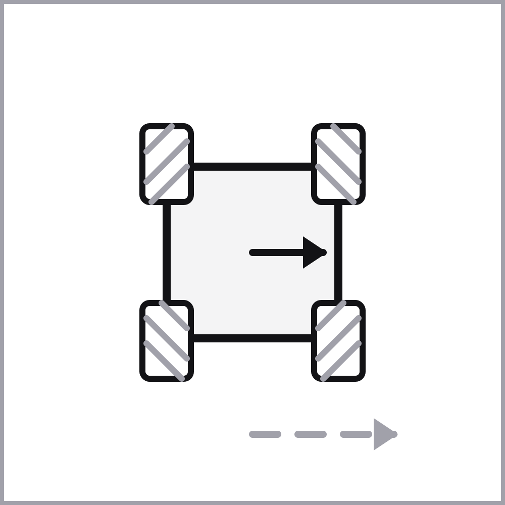
Mecanum-wheeled mobile robot platform, with the dimensions, mass and wheel geometry of the Husarion ROSbot XL (0.332 x 0.325 x 0.1335 m, 5.38 kg with the mecanum wheels and a Raspberry Pi 4, wheels of radius 0.05 m separated by 0.170 m along and 0.270 m across the platform), driven by the forces
with the viscous rolling resistance
A mecanum wheel carries rollers at 45 degrees to its rim, so it constrains only the velocity component along its own drive direction and slips freely along the rollers; the front-left and rear-right wheels share one roller diagonal, the front-right and rear-left the other. The rolling speed of each wheel is therefore
and the wrench the wheels produce is
The pose, the velocities and the yaw rate are outputs; the wheel speeds ACADOSMPCOmniRobotExample.
Usage
MPCComponents.Examples.OmniRobotPlant(m=5.38, a_max=1.0, body_length=0.332, body_width=0.325, body_height=0.1335, lx=0.085, ly=0.135, wheel_radius=0.05, wheel_width=0.045, L=lx + ly, J=m * (body_length * body_length + body_width * body_width) / 12, f_max=m * a_max / 4, b=1.0, b_om=0.05, px0=0.0, py0=0.0, th0=0.0, vx0=0.0, vy0=0.0, om0=0.0)
Parameters:
| Name | Description | Units | Default value |
|---|---|---|---|
m | Mass of the platform | – | 5.38 |
a_max | Acceleration limit of the platform | – | 1.0 |
body_length | Length of the chassis | – | 0.332 |
body_width | Width of the chassis | – | 0.325 |
body_height | Height of the chassis | – | 0.1335 |
lx | Longitudinal offset of each wheel from the centre of the platform | – | 0.085 |
ly | Lateral offset of each wheel from the centre of the platform | – | 0.135 |
wheel_radius | Radius of the mecanum wheels | – | 0.05 |
wheel_width | Width of the mecanum wheels | – | 0.045 |
b | Viscous rolling resistance | – | 1.0 |
b_om | Viscous yaw damping | – | 0.05 |
px0 | Initial position along the corridor | – | 0.0 |
py0 | Initial position across the corridor | – | 0.0 |
th0 | Initial heading | – | 0.0 |
vx0 | Initial forward velocity | – | 0.0 |
vy0 | Initial lateral velocity | – | 0.0 |
om0 | Initial yaw rate | – | 0.0 |
Connectors
f1- This connector represents a real signal as an input to a component (RealInput)f2- This connector represents a real signal as an input to a component (RealInput)f3- This connector represents a real signal as an input to a component (RealInput)f4- This connector represents a real signal as an input to a component (RealInput)px_out- This connector represents a real signal as an output from a component (RealOutput)py_out- This connector represents a real signal as an output from a component (RealOutput)th_out- This connector represents a real signal as an output from a component (RealOutput)vx_out- This connector represents a real signal as an output from a component (RealOutput)vy_out- This connector represents a real signal as an output from a component (RealOutput)om_out- This connector represents a real signal as an output from a component (RealOutput)
Variables
| Name | Description | Units |
|---|---|---|
px | Position along the corridor | – |
py | Position across the corridor | – |
th | Heading | – |
vx | Forward velocity in the body frame | – |
vy | Lateral velocity in the body frame | – |
om | Yaw rate | – |
Fx | Forward force in the body frame | – |
Fy | Lateral force in the body frame | – |
tau | Yaw torque | – |
w1 | Rolling speed of the front-left wheel | – |
w2 | Rolling speed of the front-right wheel | – |
w3 | Rolling speed of the rear-left wheel | – |
w4 | Rolling speed of the rear-right wheel | – |
Behavior
Behavior of this component cannot be rendered because it includes path variables.
Source
"""
Mecanum-wheeled mobile robot platform, with the dimensions, mass and wheel geometry of the
Husarion ROSbot XL (0.332 x 0.325 x 0.1335 m, 5.38 kg with the mecanum wheels and a Raspberry Pi 4,
wheels of radius 0.05 m separated by 0.170 m along and 0.270 m across the platform), driven by the
forces ``f_1 \\ldots f_4`` that its four wheels apply along their roller-free directions. The wheels
sit at ``(\\pm l_x, \\pm l_y)`` and only the lever arm ``L = l_x + l_y`` enters the kinematics. The state is
the pose ``(p_x, p_y, \\theta)`` in the world frame together with the body-frame velocities
``(v_x, v_y, \\omega)``:

```math
\\begin{aligned}
\\dot p_x &= v_x \\cos\\theta - v_y \\sin\\theta \\\\
\\dot p_y &= v_x \\sin\\theta + v_y \\cos\\theta \\\\
\\dot\\theta &= \\omega \\\\
m \\dot v_x &= F_x + m v_y \\omega - b v_x \\\\
m \\dot v_y &= F_y - m v_x \\omega - b v_y \\\\
J \\dot\\omega &= \\tau - b_\\omega \\omega
\\end{aligned}
```

with the viscous rolling resistance ``b``, the yaw damping ``b_\\omega`` and the centripetal terms of
the rotating body frame. The yaw inertia is that of a uniform plate of the platform's footprint and
mass; the two damping coefficients are estimates, as the specification gives no figure for them.

A mecanum wheel carries rollers at 45 degrees to its rim, so it constrains only the velocity
component along its own drive direction and slips freely along the rollers; the front-left and
rear-right wheels share one roller diagonal, the front-right and rear-left the other. The rolling
speed of each wheel is therefore

```math
w = M \\begin{bmatrix} v_x \\\\ v_y \\\\ \\omega \\end{bmatrix}, \\quad
M = \\begin{bmatrix} 1 & -1 & -L \\\\ 1 & 1 & L \\\\ 1 & 1 & -L \\\\ 1 & -1 & L \\end{bmatrix}
```

and the wrench the wheels produce is ``[F_x, F_y, \\tau]^T = M^T f``. The four wheels thus actuate all
three planar degrees of freedom, which is the omni property: ``v_y`` is a free variable, whereas a
conventional wheel would impose the no-side-slip constraint that removes it. ``M^T`` has the null
direction ``f = (1, 1, -1, -1)``, along which the wheels only fight each other and produce no wrench
at all, so a controller of this plant needs a positive-definite control penalty.

The pose, the velocities and the yaw rate are outputs; the wheel speeds ``w_1 \\ldots w_4`` are
available as variables. Every figure of the platform is a parameter here, the chassis dimensions and
the wheel offsets and radius included, so that the visualization draws the platform from the values
the simulation was run with rather than from constants of its own. The lever arm ``L = l_x + l_y``,
the yaw inertia ``J = m (\\ell^2 + w^2)/12`` of the chassis taken as a uniform plate and the force
bound of one wheel ``f_\\mathrm{max} = m a_\\mathrm{max}/4`` are derived from them. Used by
`ACADOSMPCOmniRobotExample`.
"""
component OmniRobotPlant
  "Drive force of the front-left wheel"
  f1 = RealInput() {
    "Dyad": {"placement": {"diagram": {"x1": -100, "x2": 0, "y1": 100, "y2": 200}}}
  }
  "Drive force of the front-right wheel"
  f2 = RealInput() {
    "Dyad": {"placement": {"diagram": {"x1": -100, "x2": 0, "y1": 330, "y2": 430}}}
  }
  "Drive force of the rear-left wheel"
  f3 = RealInput() {
    "Dyad": {"placement": {"diagram": {"x1": -100, "x2": 0, "y1": 560, "y2": 660}}}
  }
  "Drive force of the rear-right wheel"
  f4 = RealInput() {
    "Dyad": {"placement": {"diagram": {"x1": -100, "x2": 0, "y1": 790, "y2": 890}}}
  }
  "Position along the corridor"
  px_out = RealOutput() {
    "Dyad": {"placement": {"diagram": {"x1": 1000, "x2": 1100, "y1": 50, "y2": 150}}}
  }
  "Position across the corridor"
  py_out = RealOutput() {
    "Dyad": {"placement": {"diagram": {"x1": 1000, "x2": 1100, "y1": 200, "y2": 300}}}
  }
  "Heading"
  th_out = RealOutput() {
    "Dyad": {"placement": {"diagram": {"x1": 1000, "x2": 1100, "y1": 350, "y2": 450}}}
  }
  "Forward velocity in the body frame"
  vx_out = RealOutput() {
    "Dyad": {"placement": {"diagram": {"x1": 1000, "x2": 1100, "y1": 500, "y2": 600}}}
  }
  "Lateral velocity in the body frame"
  vy_out = RealOutput() {
    "Dyad": {"placement": {"diagram": {"x1": 1000, "x2": 1100, "y1": 650, "y2": 750}}}
  }
  "Yaw rate"
  om_out = RealOutput() {
    "Dyad": {"placement": {"diagram": {"x1": 1000, "x2": 1100, "y1": 800, "y2": 900}}}
  }
  "Mass of the platform"
  parameter m::Real = 5.38
  "Acceleration limit of the platform"
  parameter a_max::Real = 1.0
  "Length of the chassis"
  parameter body_length::Real = 0.332
  "Width of the chassis"
  parameter body_width::Real = 0.325
  "Height of the chassis"
  parameter body_height::Real = 0.1335
  "Longitudinal offset of each wheel from the centre of the platform"
  parameter lx::Real = 0.085
  "Lateral offset of each wheel from the centre of the platform"
  parameter ly::Real = 0.135
  "Radius of the mecanum wheels"
  parameter wheel_radius::Real = 0.05
  "Width of the mecanum wheels"
  parameter wheel_width::Real = 0.045
  "Lever arm of the wheels, the sum of their two offsets (derived)"
  final parameter L::Real = lx + ly
  "Yaw inertia of the platform, its chassis taken as a uniform plate (derived)"
  final parameter J::Real = m * (body_length * body_length + body_width * body_width) / 12
  "Force bound of one wheel, the acceleration limit of the platform spread over its four wheels (derived)"
  final parameter f_max::Real = m * a_max / 4
  "Viscous rolling resistance"
  parameter b::Real = 1.0
  "Viscous yaw damping"
  parameter b_om::Real = 0.05
  "Initial position along the corridor"
  parameter px0::Real = 0.0
  "Initial position across the corridor"
  parameter py0::Real = 0.0
  "Initial heading"
  parameter th0::Real = 0.0
  "Initial forward velocity"
  parameter vx0::Real = 0.0
  "Initial lateral velocity"
  parameter vy0::Real = 0.0
  "Initial yaw rate"
  parameter om0::Real = 0.0
  "Position along the corridor"
  variable px::Real
  "Position across the corridor"
  variable py::Real
  "Heading"
  variable th::Real
  "Forward velocity in the body frame"
  variable vx::Real
  "Lateral velocity in the body frame"
  variable vy::Real
  "Yaw rate"
  variable om::Real
  "Forward force in the body frame"
  variable Fx::Real
  "Lateral force in the body frame"
  variable Fy::Real
  "Yaw torque"
  variable tau::Real
  "Rolling speed of the front-left wheel"
  variable w1::Real
  "Rolling speed of the front-right wheel"
  variable w2::Real
  "Rolling speed of the rear-left wheel"
  variable w3::Real
  "Rolling speed of the rear-right wheel"
  variable w4::Real
relations
  initial px = px0
  initial py = py0
  initial th = th0
  initial vx = vx0
  initial vy = vy0
  initial om = om0
  Fx = f1 + f2 + f3 + f4
  Fy = -f1 + f2 + f3 - f4
  tau = L * (-f1 + f2 - f3 + f4)
  w1 = vx - vy - L * om
  w2 = vx + vy + L * om
  w3 = vx + vy - L * om
  w4 = vx - vy + L * om
  der(px) = vx * cos(th) - vy * sin(th)
  der(py) = vx * sin(th) + vy * cos(th)
  der(th) = om
  m * der(vx) = Fx + m * vy * om - b * vx
  m * der(vy) = Fy - m * vx * om - b * vy
  J * der(om) = tau - b_om * om
  px_out = px
  py_out = py
  th_out = th
  vx_out = vx
  vy_out = vy
  om_out = om
metadata {
  "Dyad": {
    "icons": {"default": "dyad://MPCComponents/OmniRobotPlant.svg"},
    "doc": {"behavior": false}
  }
}
end
Flattened Source
"""
Mecanum-wheeled mobile robot platform, with the dimensions, mass and wheel geometry of the
Husarion ROSbot XL (0.332 x 0.325 x 0.1335 m, 5.38 kg with the mecanum wheels and a Raspberry Pi 4,
wheels of radius 0.05 m separated by 0.170 m along and 0.270 m across the platform), driven by the
forces ``f_1 \\ldots f_4`` that its four wheels apply along their roller-free directions. The wheels
sit at ``(\\pm l_x, \\pm l_y)`` and only the lever arm ``L = l_x + l_y`` enters the kinematics. The state is
the pose ``(p_x, p_y, \\theta)`` in the world frame together with the body-frame velocities
``(v_x, v_y, \\omega)``:

```math
\\begin{aligned}
\\dot p_x &= v_x \\cos\\theta - v_y \\sin\\theta \\\\
\\dot p_y &= v_x \\sin\\theta + v_y \\cos\\theta \\\\
\\dot\\theta &= \\omega \\\\
m \\dot v_x &= F_x + m v_y \\omega - b v_x \\\\
m \\dot v_y &= F_y - m v_x \\omega - b v_y \\\\
J \\dot\\omega &= \\tau - b_\\omega \\omega
\\end{aligned}
```

with the viscous rolling resistance ``b``, the yaw damping ``b_\\omega`` and the centripetal terms of
the rotating body frame. The yaw inertia is that of a uniform plate of the platform's footprint and
mass; the two damping coefficients are estimates, as the specification gives no figure for them.

A mecanum wheel carries rollers at 45 degrees to its rim, so it constrains only the velocity
component along its own drive direction and slips freely along the rollers; the front-left and
rear-right wheels share one roller diagonal, the front-right and rear-left the other. The rolling
speed of each wheel is therefore

```math
w = M \\begin{bmatrix} v_x \\\\ v_y \\\\ \\omega \\end{bmatrix}, \\quad
M = \\begin{bmatrix} 1 & -1 & -L \\\\ 1 & 1 & L \\\\ 1 & 1 & -L \\\\ 1 & -1 & L \\end{bmatrix}
```

and the wrench the wheels produce is ``[F_x, F_y, \\tau]^T = M^T f``. The four wheels thus actuate all
three planar degrees of freedom, which is the omni property: ``v_y`` is a free variable, whereas a
conventional wheel would impose the no-side-slip constraint that removes it. ``M^T`` has the null
direction ``f = (1, 1, -1, -1)``, along which the wheels only fight each other and produce no wrench
at all, so a controller of this plant needs a positive-definite control penalty.

The pose, the velocities and the yaw rate are outputs; the wheel speeds ``w_1 \\ldots w_4`` are
available as variables. Every figure of the platform is a parameter here, the chassis dimensions and
the wheel offsets and radius included, so that the visualization draws the platform from the values
the simulation was run with rather than from constants of its own. The lever arm ``L = l_x + l_y``,
the yaw inertia ``J = m (\\ell^2 + w^2)/12`` of the chassis taken as a uniform plate and the force
bound of one wheel ``f_\\mathrm{max} = m a_\\mathrm{max}/4`` are derived from them. Used by
`ACADOSMPCOmniRobotExample`.
"""
component OmniRobotPlant
  "Drive force of the front-left wheel"
  f1 = RealInput() {
    "Dyad": {"placement": {"diagram": {"x1": -100, "x2": 0, "y1": 100, "y2": 200}}}
  }
  "Drive force of the front-right wheel"
  f2 = RealInput() {
    "Dyad": {"placement": {"diagram": {"x1": -100, "x2": 0, "y1": 330, "y2": 430}}}
  }
  "Drive force of the rear-left wheel"
  f3 = RealInput() {
    "Dyad": {"placement": {"diagram": {"x1": -100, "x2": 0, "y1": 560, "y2": 660}}}
  }
  "Drive force of the rear-right wheel"
  f4 = RealInput() {
    "Dyad": {"placement": {"diagram": {"x1": -100, "x2": 0, "y1": 790, "y2": 890}}}
  }
  "Position along the corridor"
  px_out = RealOutput() {
    "Dyad": {"placement": {"diagram": {"x1": 1000, "x2": 1100, "y1": 50, "y2": 150}}}
  }
  "Position across the corridor"
  py_out = RealOutput() {
    "Dyad": {"placement": {"diagram": {"x1": 1000, "x2": 1100, "y1": 200, "y2": 300}}}
  }
  "Heading"
  th_out = RealOutput() {
    "Dyad": {"placement": {"diagram": {"x1": 1000, "x2": 1100, "y1": 350, "y2": 450}}}
  }
  "Forward velocity in the body frame"
  vx_out = RealOutput() {
    "Dyad": {"placement": {"diagram": {"x1": 1000, "x2": 1100, "y1": 500, "y2": 600}}}
  }
  "Lateral velocity in the body frame"
  vy_out = RealOutput() {
    "Dyad": {"placement": {"diagram": {"x1": 1000, "x2": 1100, "y1": 650, "y2": 750}}}
  }
  "Yaw rate"
  om_out = RealOutput() {
    "Dyad": {"placement": {"diagram": {"x1": 1000, "x2": 1100, "y1": 800, "y2": 900}}}
  }
  "Mass of the platform"
  parameter m::Real = 5.38
  "Acceleration limit of the platform"
  parameter a_max::Real = 1.0
  "Length of the chassis"
  parameter body_length::Real = 0.332
  "Width of the chassis"
  parameter body_width::Real = 0.325
  "Height of the chassis"
  parameter body_height::Real = 0.1335
  "Longitudinal offset of each wheel from the centre of the platform"
  parameter lx::Real = 0.085
  "Lateral offset of each wheel from the centre of the platform"
  parameter ly::Real = 0.135
  "Radius of the mecanum wheels"
  parameter wheel_radius::Real = 0.05
  "Width of the mecanum wheels"
  parameter wheel_width::Real = 0.045
  "Lever arm of the wheels, the sum of their two offsets (derived)"
  final parameter L::Real = lx + ly
  "Yaw inertia of the platform, its chassis taken as a uniform plate (derived)"
  final parameter J::Real = m * (body_length * body_length + body_width * body_width) / 12
  "Force bound of one wheel, the acceleration limit of the platform spread over its four wheels (derived)"
  final parameter f_max::Real = m * a_max / 4
  "Viscous rolling resistance"
  parameter b::Real = 1.0
  "Viscous yaw damping"
  parameter b_om::Real = 0.05
  "Initial position along the corridor"
  parameter px0::Real = 0.0
  "Initial position across the corridor"
  parameter py0::Real = 0.0
  "Initial heading"
  parameter th0::Real = 0.0
  "Initial forward velocity"
  parameter vx0::Real = 0.0
  "Initial lateral velocity"
  parameter vy0::Real = 0.0
  "Initial yaw rate"
  parameter om0::Real = 0.0
  "Position along the corridor"
  variable px::Real
  "Position across the corridor"
  variable py::Real
  "Heading"
  variable th::Real
  "Forward velocity in the body frame"
  variable vx::Real
  "Lateral velocity in the body frame"
  variable vy::Real
  "Yaw rate"
  variable om::Real
  "Forward force in the body frame"
  variable Fx::Real
  "Lateral force in the body frame"
  variable Fy::Real
  "Yaw torque"
  variable tau::Real
  "Rolling speed of the front-left wheel"
  variable w1::Real
  "Rolling speed of the front-right wheel"
  variable w2::Real
  "Rolling speed of the rear-left wheel"
  variable w3::Real
  "Rolling speed of the rear-right wheel"
  variable w4::Real
relations
  initial px = px0
  initial py = py0
  initial th = th0
  initial vx = vx0
  initial vy = vy0
  initial om = om0
  Fx = f1 + f2 + f3 + f4
  Fy = -f1 + f2 + f3 - f4
  tau = L * (-f1 + f2 - f3 + f4)
  w1 = vx - vy - L * om
  w2 = vx + vy + L * om
  w3 = vx + vy - L * om
  w4 = vx - vy + L * om
  der(px) = vx * cos(th) - vy * sin(th)
  der(py) = vx * sin(th) + vy * cos(th)
  der(th) = om
  m * der(vx) = Fx + m * vy * om - b * vx
  m * der(vy) = Fy - m * vx * om - b * vy
  J * der(om) = tau - b_om * om
  px_out = px
  py_out = py
  th_out = th
  vx_out = vx
  vy_out = vy
  om_out = om
metadata {
  "Dyad": {
    "icons": {"default": "dyad://MPCComponents/OmniRobotPlant.svg"},
    "doc": {"behavior": false}
  }
}
end
Test Cases
No test cases defined.
Related
Examples
Experiments
Analyses