

Analog.Examples.ThermalRunaway
Thermal runaway in a fixed-V_BE bipolar stage.
A demonstration of the electro-thermal feedback loop that the heat port and the temperature model make possible. The loop is:
the saturation current climbs steeply with temperature,
I_s(T) = I_s (T/T_{NOM})^{XTI} e^{(E_G/V_T)(T/T_{NOM}-1)}at fixed base-emitter voltage, collector current follows it directly
more current means more dissipation, reported as
LossPowerthe heat port carries that into the thermal network, raising
Tback to 1
Whether this settles or diverges is decided by the loop gain, and the term the user controls is the thermal resistance R_th. Small R_th — a good heatsink — and the junction barely warms. Large R_th and the stage walks itself up until the collector load finally limits the current.
Why fixed V_BE is the interesting bias
Nothing here pushes back. Drive the base from a stiff current source instead and I_c = Bf I_b pins the current regardless of temperature, so there is no runaway — with XTB = 0 the betas do not even drift. Add an emitter resistor and rising current lifts the emitter, cutting V_BE and closing the loop down. That degeneration resistor is why it appears in every real bias network, and this example is what it is defending against.
The circuit
   V_CC ──[R_C]──┬──── c              port ──── HeatCapacitor(C_th)
                 │     │                              │
   V_BE ──[R_B]──┼──── b                       ThermalConductor(G = 1/R_th)
                 │     │                              │
                gnd   gnd                      FixedTemperature(T_ambient)
R_B is deliberately small — ten ohms at tens of microamps is a fraction of a millivolt, so V_BE is still effectively pinned. It is present because an ideal source placed directly across the base-emitter junction also sits directly across C_jE, which is a structurally singular configuration.
Measured behavior
Sweeping R_th at the default bias, to 60 s:
R_th [K/W] | 300 | 600 | 900 | 1100 | 2000 |
|---|---|---|---|---|---|
| ΔT [K] | 5.78 | 113.5 | 120.0 | 122.1 | 126.1 |
I_c [mA] | 1.96 | 74.9 | 84.3 | 87.5 | 93.4 |
So the boundary sits between 300 and 600 K/W. A linear criterion evaluated at ambient — R_th dP/dT > 1, with dP/dT ≈ 0.94 mW/K here — would predict about 1060 K/W and be roughly a factor of two too high. That is because dP/dT itself climbs steeply with temperature: by the time ΔT is a few tens of kelvin the gain is several times larger. Onset is really a saddle-node bifurcation, the point at which the cool solution stops existing, not the point where the gain at ambient reaches one.
Why the runaway stops
There is no destruction mechanism, and the load line ends it before anything else would. Dissipation is
a downward parabola in I_c peaking at I_c = V_{CC}/2R_C — 50 mA here, where V_CE = 5 V and P = 250 mW. Past that peak more current means less dissipation, so dP/dT turns negative and the loop becomes negative feedback. That is what arrests the runaway: the device crossing the power maximum, not V_CE reaching zero. At R_th = 2000 it ends at I_c = 93.4 mA, V_CE = 0.66 V, P = 63 mW, well down the falling side.
The same parabola makes the worst case interior in the drive as well:
V_BE | 0.78 | 0.82 | 0.85 | 0.88 |
|---|---|---|---|---|
| ΔT [K] | 5.78 | 69.2 | 50.6 | 28.3 |
| P [mW] | 19.3 | 230.6 | 168.8 | 94.2 |
A real device would have crossed its junction temperature rating around V_BE = 0.82 and failed. This one settles at a new, much hotter operating point instead. The runaway is the transition, not an asymptote.
Usage
ElectricalComponents.Analog.Examples.ThermalRunaway(R_th=600.0, V_BE_drive=0.78, V_CC=10.0, R_C=100.0, C_th=2.0e-3, T_ambient=300.15)
Parameters:
| Name | Description | Units | Default value |
|---|---|---|---|
R_th | Junction-to-ambient thermal resistance. The knob that decides the outcome. The default runs away. Set R_th = 300 for the stable comparison. | K/W | 600.0 |
V_BE_drive | Base-emitter drive, held fixed. Dimensionless: it feeds a signal-level Constant. | – | 0.78 |
V_CC | Collector supply | – | 10.0 |
R_C | Collector load | Ω | 100.0 |
C_th | Thermal mass of the junction and its package | J/K | 2.0e-3 |
T_ambient | Ambient temperature | K | 300.15 |
Behavior
Source
"""
Thermal runaway in a fixed-`V_BE` bipolar stage.

A demonstration of the electro-thermal feedback loop that the heat port and the
temperature model make possible.  The loop is:

  1. the saturation current climbs steeply with temperature,
     `I_s(T) = I_s (T/T_{NOM})^{XTI} e^{(E_G/V_T)(T/T_{NOM}-1)}`
  2. at *fixed* base-emitter voltage, collector current follows it directly
  3. more current means more dissipation, reported as `LossPower`
  4. the heat port carries that into the thermal network, raising `T`
  5. back to 1

Whether this settles or diverges is decided by the loop gain, and the term the
user controls is the thermal resistance `R_th`.  Small `R_th` — a good heatsink —
and the junction barely warms.  Large `R_th` and the stage walks itself up until
the collector load finally limits the current.

## Why fixed `V_BE` is the interesting bias

Nothing here pushes back.  Drive the base from a stiff current source instead and
`I_c = Bf I_b` pins the current regardless of temperature, so there is no
runaway — with `XTB = 0` the betas do not even drift.  Add an emitter resistor
and rising current lifts the emitter, cutting `V_BE` and closing the loop down.
That degeneration resistor is *why* it appears in every real bias network, and
this example is what it is defending against.

## The circuit

```
   V_CC ──[R_C]──┬──── c              port ──── HeatCapacitor(C_th)
                 │     │                              │
   V_BE ──[R_B]──┼──── b                       ThermalConductor(G = 1/R_th)
                 │     │                              │
                gnd   gnd                      FixedTemperature(T_ambient)
```

`R_B` is deliberately small — ten ohms at tens of microamps is a fraction of a
millivolt, so `V_BE` is still effectively pinned.  It is present because an ideal
source placed directly across the base-emitter junction also sits directly across
`C_jE`, which is a structurally singular configuration.

## Measured behavior

Sweeping `R_th` at the default bias, to 60 s:

| `R_th` [K/W] | 300 | 600 | 900 | 1100 | 2000 |
| --- | --- | --- | --- | --- | --- |
| ΔT [K] | 5.78 | 113.5 | 120.0 | 122.1 | 126.1 |
| `I_c` [mA] | 1.96 | 74.9 | 84.3 | 87.5 | 93.4 |

So the boundary sits between 300 and 600 K/W.  A linear criterion evaluated at
ambient — `R_th dP/dT > 1`, with `dP/dT ≈ 0.94 mW/K` here — would predict about
1060 K/W and be roughly a factor of two too high.  That is because `dP/dT`
itself climbs steeply with temperature: by the time ΔT is a few tens of kelvin
the gain is several times larger.  Onset is really a saddle-node bifurcation,
the point at which the cool solution stops existing, not the point where the
gain at ambient reaches one.

## Why the runaway stops

There is no destruction mechanism, and the *load line* ends it before anything
else would.  Dissipation is
```math
P = I_c V_{CE} = I_c \\left( V_{CC} - I_c R_C \\right)
```
a downward parabola in `I_c` peaking at `I_c = V_{CC}/2R_C` — 50 mA here, where
`V_CE = 5 V` and `P = 250 mW`.  Past that peak **more current means less
dissipation**, so `dP/dT` turns negative and the loop becomes negative feedback.
That is what arrests the runaway: the device crossing the power maximum, not
`V_CE` reaching zero.  At `R_th = 2000` it ends at `I_c = 93.4 mA`,
`V_CE = 0.66 V`, `P = 63 mW`, well down the falling side.

The same parabola makes the worst case interior in the drive as well:

| `V_BE` | 0.78 | 0.82 | 0.85 | 0.88 |
| --- | --- | --- | --- | --- |
| ΔT [K] | 5.78 | 69.2 | 50.6 | 28.3 |
| P [mW] | 19.3 | 230.6 | 168.8 | 94.2 |

A real device would have crossed its junction temperature rating around
`V_BE = 0.82` and failed.  This one settles at a new, much hotter operating
point instead.  The runaway is the *transition*, not an asymptote.
"""
example component ThermalRunaway
  "The device under test, thermally coupled"
  transistor = ElectricalComponents.Analog.Semiconductors.NPN(use_heat_port = true, use_temperature_dependency = true) {
    "Dyad": {"placement": {"diagram": {"x1": 415, "x2": 515, "y1": 441, "y2": 541}}}
  }
  "Collector load resistor"
  load = ElectricalComponents.Analog.Basic.Resistor(R = R_C) {
    "Dyad": {"placement": {"diagram": {"x1": 285, "x2": 385, "y1": 226, "y2": 326}}}
  }
  "Small base series resistance; keeps the base off an ideal source"
  base_r = ElectricalComponents.Analog.Basic.Resistor(R = 10.0) {
    "Dyad": {"placement": {"diagram": {"x1": 285, "x2": 385, "y1": 441, "y2": 541}}}
  }
  "Collector supply"
  supply = ElectricalComponents.Analog.Sources.VoltageSource() {
    "Dyad": {"placement": {"diagram": {"x1": 155, "x2": 255, "y1": 125, "y2": 225}}}
  }
  "Supply level"
  supply_level = BlockComponents.Sources.Constant(k = V_CC) {"Dyad": {"placement": {"diagram": {"x1": 20, "x2": 120, "y1": 20, "y2": 120}}}}
  "Fixed base-emitter drive"
  bias = ElectricalComponents.Analog.Sources.VoltageSource() {
    "Dyad": {"placement": {"diagram": {"x1": 155, "x2": 255, "y1": 341, "y2": 441}}}
  }
  "Drive level"
  bias_level = BlockComponents.Sources.Constant(k = V_BE_drive) {
    "Dyad": {"placement": {"diagram": {"x1": 20, "x2": 120, "y1": 236, "y2": 336}}}
  }
  "Electrical reference"
  gnd = ElectricalComponents.Analog.Basic.Ground() {
    "Dyad": {"placement": {"diagram": {"x1": 542.5, "x2": 642.5, "y1": 230, "y2": 330}}}
  }
  "Junction and package thermal mass"
  mass = ThermalComponents.Components.HeatCapacitor(C = C_th, T0 = T_ambient) {
    "Dyad": {"placement": {"diagram": {"x1": 542.5, "x2": 642.5, "y1": 470, "y2": 570}}}
  }
  "Heatsink path to ambient; G is the reciprocal of the datasheet R_th"
  sink = ThermalComponents.Components.ThermalConductor(G = 1.0 / R_th) {
    "Dyad": {"placement": {"diagram": {"x1": 670, "x2": 770, "y1": 575, "y2": 675}}}
  }
  "Ambient reservoir"
  ambient = ThermalComponents.Sources.FixedTemperature(T = T_ambient) {
    "Dyad": {"placement": {"diagram": {"x1": 540, "x2": 640, "y1": 350, "y2": 450}}}
  }
  """
  Junction-to-ambient thermal resistance. The knob that decides the outcome.
  The default runs away. Set `R_th = 300` for the stable comparison.
  """
  parameter R_th::Real(units = "K/W") = 600.0
  "Base-emitter drive, held fixed. Dimensionless: it feeds a signal-level Constant."
  parameter V_BE_drive::Real = 0.78
  "Collector supply"
  parameter V_CC::Real = 10.0
  "Collector load"
  parameter R_C::Resistance = 100.0
  "Thermal mass of the junction and its package"
  parameter C_th::HeatCapacity = 2.0e-3
  "Ambient temperature"
  parameter T_ambient::Temperature = 300.15
relations
  initial transistor.V_BE = V_BE_drive
  initial transistor.V_BC = V_BE_drive - V_CC
  "Signal levels into the two sources"
  connect(supply_level.y, supply.V) {"Dyad": {"edges": [{"S": 1, "M": [{"x": 205, "y": 70}], "E": 2}], "path": {}}}
  connect(bias_level.y, bias.V) {"Dyad": {"edges": [{"S": 1, "M": [{"x": 205, "y": 286}], "E": 2}], "path": {}}}
  "Collector load"
  connect(supply.p, load.p) {
    "Dyad": {
      "edges": [{"S": 1, "M": [{"x": 140, "y": 175}, {"x": 140, "y": 276}], "E": 2}],
      "path": {}
    }
  }
  connect(load.n, transistor.c) {"Dyad": {"edges": [{"S": 1, "M": [{"x": 465, "y": 276}], "E": 2}], "path": {}}}
  "Fixed base drive through a small series resistance"
  connect(bias.p, base_r.p) {
    "Dyad": {
      "edges": [{"S": 1, "M": [{"x": 140, "y": 391}, {"x": 140, "y": 491}], "E": 2}],
      "path": {}
    }
  }
  connect(base_r.n, transistor.b) {"Dyad": {"edges": [{"S": 1, "M": [], "E": 2}], "path": {}}}
  "Emitter and substrate to ground"
  connect(transistor.e, gnd.g) {
    "Dyad": {
      "edges": [
        {"S": 1, "M": [{"x": 465, "y": 596}, {"x": 530, "y": 596}], "E": -1},
        {"S": -1, "M": [{"x": 592.5, "y": 175}], "E": 2}
      ],
      "junctions": [{"x": 530, "y": 175}],
      "path": {}
    }
  }
  connect(transistor.s, gnd.g) {
    "Dyad": {
      "edges": [
        {"S": 1, "M": [], "E": -1},
        {"S": -1, "M": [{"x": 530, "y": 175}, {"x": 592.5, "y": 175}], "E": 2}
      ],
      "junctions": [{"x": 530, "y": 491}],
      "path": {}
    }
  }
  connect(supply.n, gnd.g) {
    "Dyad": {"edges": [{"S": 1, "M": [{"x": 592.5, "y": 175}], "E": 2}], "path": {}}
  }
  connect(bias.n, gnd.g) {
    "Dyad": {
      "edges": [
        {"S": 1, "M": [{"x": 270, "y": 391}], "E": -1},
        {"S": -1, "M": [{"x": 592.5, "y": 175}], "E": 2}
      ],
      "junctions": [{"x": 270, "y": 175}],
      "path": {}
    }
  }
  "Thermal path: junction into the mass, mass to ambient through the heatsink"
  connect(transistor.port, mass.port) {
    "Dyad": {
      "edges": [
        {"S": 1, "M": [{"x": 400, "y": 521}, {"x": 400, "y": 625}], "E": -1},
        {"S": -1, "M": [], "E": 2}
      ],
      "junctions": [{"x": 592.5, "y": 625}],
      "path": {}
    }
  }
  connect(mass.port, sink.port_a) {
    "Dyad": {
      "edges": [{"S": 1, "M": [], "E": -1}, {"S": -1, "M": [], "E": 2}],
      "junctions": [{"x": 592.5, "y": 625}],
      "path": {}
    }
  }
  connect(sink.port_b, ambient.port) {
    "Dyad": {
      "edges": [{"S": 1, "M": [{"x": 785, "y": 625}, {"x": 785, "y": 400}], "E": 2}],
      "path": {}
    }
  }
metadata {
  "Dyad": {
    "icons": {"default": "dyad://ElectricalComponents/Example.svg"},
    "tests": {
      "case1": {
        "stop": 60,
        "abstol": 1e-8,
        "reltol": 0.000001,
        "expect": {"signals": ["transistor.T_dev", "transistor.LossPower"]}
      }
    }
  }
}
end
Flattened Source
"""
Thermal runaway in a fixed-`V_BE` bipolar stage.

A demonstration of the electro-thermal feedback loop that the heat port and the
temperature model make possible.  The loop is:

  1. the saturation current climbs steeply with temperature,
     `I_s(T) = I_s (T/T_{NOM})^{XTI} e^{(E_G/V_T)(T/T_{NOM}-1)}`
  2. at *fixed* base-emitter voltage, collector current follows it directly
  3. more current means more dissipation, reported as `LossPower`
  4. the heat port carries that into the thermal network, raising `T`
  5. back to 1

Whether this settles or diverges is decided by the loop gain, and the term the
user controls is the thermal resistance `R_th`.  Small `R_th` — a good heatsink —
and the junction barely warms.  Large `R_th` and the stage walks itself up until
the collector load finally limits the current.

## Why fixed `V_BE` is the interesting bias

Nothing here pushes back.  Drive the base from a stiff current source instead and
`I_c = Bf I_b` pins the current regardless of temperature, so there is no
runaway — with `XTB = 0` the betas do not even drift.  Add an emitter resistor
and rising current lifts the emitter, cutting `V_BE` and closing the loop down.
That degeneration resistor is *why* it appears in every real bias network, and
this example is what it is defending against.

## The circuit

```
   V_CC ──[R_C]──┬──── c              port ──── HeatCapacitor(C_th)
                 │     │                              │
   V_BE ──[R_B]──┼──── b                       ThermalConductor(G = 1/R_th)
                 │     │                              │
                gnd   gnd                      FixedTemperature(T_ambient)
```

`R_B` is deliberately small — ten ohms at tens of microamps is a fraction of a
millivolt, so `V_BE` is still effectively pinned.  It is present because an ideal
source placed directly across the base-emitter junction also sits directly across
`C_jE`, which is a structurally singular configuration.

## Measured behavior

Sweeping `R_th` at the default bias, to 60 s:

| `R_th` [K/W] | 300 | 600 | 900 | 1100 | 2000 |
| --- | --- | --- | --- | --- | --- |
| ΔT [K] | 5.78 | 113.5 | 120.0 | 122.1 | 126.1 |
| `I_c` [mA] | 1.96 | 74.9 | 84.3 | 87.5 | 93.4 |

So the boundary sits between 300 and 600 K/W.  A linear criterion evaluated at
ambient — `R_th dP/dT > 1`, with `dP/dT ≈ 0.94 mW/K` here — would predict about
1060 K/W and be roughly a factor of two too high.  That is because `dP/dT`
itself climbs steeply with temperature: by the time ΔT is a few tens of kelvin
the gain is several times larger.  Onset is really a saddle-node bifurcation,
the point at which the cool solution stops existing, not the point where the
gain at ambient reaches one.

## Why the runaway stops

There is no destruction mechanism, and the *load line* ends it before anything
else would.  Dissipation is
```math
P = I_c V_{CE} = I_c \\left( V_{CC} - I_c R_C \\right)
```
a downward parabola in `I_c` peaking at `I_c = V_{CC}/2R_C` — 50 mA here, where
`V_CE = 5 V` and `P = 250 mW`.  Past that peak **more current means less
dissipation**, so `dP/dT` turns negative and the loop becomes negative feedback.
That is what arrests the runaway: the device crossing the power maximum, not
`V_CE` reaching zero.  At `R_th = 2000` it ends at `I_c = 93.4 mA`,
`V_CE = 0.66 V`, `P = 63 mW`, well down the falling side.

The same parabola makes the worst case interior in the drive as well:

| `V_BE` | 0.78 | 0.82 | 0.85 | 0.88 |
| --- | --- | --- | --- | --- |
| ΔT [K] | 5.78 | 69.2 | 50.6 | 28.3 |
| P [mW] | 19.3 | 230.6 | 168.8 | 94.2 |

A real device would have crossed its junction temperature rating around
`V_BE = 0.82` and failed.  This one settles at a new, much hotter operating
point instead.  The runaway is the *transition*, not an asymptote.
"""
example component ThermalRunaway
  "The device under test, thermally coupled"
  transistor = ElectricalComponents.Analog.Semiconductors.NPN(use_heat_port = true, use_temperature_dependency = true) {
    "Dyad": {"placement": {"diagram": {"x1": 415, "x2": 515, "y1": 441, "y2": 541}}}
  }
  "Collector load resistor"
  load = ElectricalComponents.Analog.Basic.Resistor(R = R_C) {
    "Dyad": {"placement": {"diagram": {"x1": 285, "x2": 385, "y1": 226, "y2": 326}}}
  }
  "Small base series resistance; keeps the base off an ideal source"
  base_r = ElectricalComponents.Analog.Basic.Resistor(R = 10.0) {
    "Dyad": {"placement": {"diagram": {"x1": 285, "x2": 385, "y1": 441, "y2": 541}}}
  }
  "Collector supply"
  supply = ElectricalComponents.Analog.Sources.VoltageSource() {
    "Dyad": {"placement": {"diagram": {"x1": 155, "x2": 255, "y1": 125, "y2": 225}}}
  }
  "Supply level"
  supply_level = BlockComponents.Sources.Constant(k = V_CC) {"Dyad": {"placement": {"diagram": {"x1": 20, "x2": 120, "y1": 20, "y2": 120}}}}
  "Fixed base-emitter drive"
  bias = ElectricalComponents.Analog.Sources.VoltageSource() {
    "Dyad": {"placement": {"diagram": {"x1": 155, "x2": 255, "y1": 341, "y2": 441}}}
  }
  "Drive level"
  bias_level = BlockComponents.Sources.Constant(k = V_BE_drive) {
    "Dyad": {"placement": {"diagram": {"x1": 20, "x2": 120, "y1": 236, "y2": 336}}}
  }
  "Electrical reference"
  gnd = ElectricalComponents.Analog.Basic.Ground() {
    "Dyad": {"placement": {"diagram": {"x1": 542.5, "x2": 642.5, "y1": 230, "y2": 330}}}
  }
  "Junction and package thermal mass"
  mass = ThermalComponents.Components.HeatCapacitor(C = C_th, T0 = T_ambient) {
    "Dyad": {"placement": {"diagram": {"x1": 542.5, "x2": 642.5, "y1": 470, "y2": 570}}}
  }
  "Heatsink path to ambient; G is the reciprocal of the datasheet R_th"
  sink = ThermalComponents.Components.ThermalConductor(G = 1.0 / R_th) {
    "Dyad": {"placement": {"diagram": {"x1": 670, "x2": 770, "y1": 575, "y2": 675}}}
  }
  "Ambient reservoir"
  ambient = ThermalComponents.Sources.FixedTemperature(T = T_ambient) {
    "Dyad": {"placement": {"diagram": {"x1": 540, "x2": 640, "y1": 350, "y2": 450}}}
  }
  """
  Junction-to-ambient thermal resistance. The knob that decides the outcome.
  The default runs away. Set `R_th = 300` for the stable comparison.
  """
  parameter R_th::Real(units = "K/W") = 600.0
  "Base-emitter drive, held fixed. Dimensionless: it feeds a signal-level Constant."
  parameter V_BE_drive::Real = 0.78
  "Collector supply"
  parameter V_CC::Real = 10.0
  "Collector load"
  parameter R_C::Resistance = 100.0
  "Thermal mass of the junction and its package"
  parameter C_th::HeatCapacity = 2.0e-3
  "Ambient temperature"
  parameter T_ambient::Temperature = 300.15
relations
  initial transistor.V_BE = V_BE_drive
  initial transistor.V_BC = V_BE_drive - V_CC
  "Signal levels into the two sources"
  connect(supply_level.y, supply.V) {"Dyad": {"edges": [{"S": 1, "M": [{"x": 205, "y": 70}], "E": 2}], "path": {}}}
  connect(bias_level.y, bias.V) {"Dyad": {"edges": [{"S": 1, "M": [{"x": 205, "y": 286}], "E": 2}], "path": {}}}
  "Collector load"
  connect(supply.p, load.p) {
    "Dyad": {
      "edges": [{"S": 1, "M": [{"x": 140, "y": 175}, {"x": 140, "y": 276}], "E": 2}],
      "path": {}
    }
  }
  connect(load.n, transistor.c) {"Dyad": {"edges": [{"S": 1, "M": [{"x": 465, "y": 276}], "E": 2}], "path": {}}}
  "Fixed base drive through a small series resistance"
  connect(bias.p, base_r.p) {
    "Dyad": {
      "edges": [{"S": 1, "M": [{"x": 140, "y": 391}, {"x": 140, "y": 491}], "E": 2}],
      "path": {}
    }
  }
  connect(base_r.n, transistor.b) {"Dyad": {"edges": [{"S": 1, "M": [], "E": 2}], "path": {}}}
  "Emitter and substrate to ground"
  connect(transistor.e, gnd.g) {
    "Dyad": {
      "edges": [
        {"S": 1, "M": [{"x": 465, "y": 596}, {"x": 530, "y": 596}], "E": -1},
        {"S": -1, "M": [{"x": 592.5, "y": 175}], "E": 2}
      ],
      "junctions": [{"x": 530, "y": 175}],
      "path": {}
    }
  }
  connect(transistor.s, gnd.g) {
    "Dyad": {
      "edges": [
        {"S": 1, "M": [], "E": -1},
        {"S": -1, "M": [{"x": 530, "y": 175}, {"x": 592.5, "y": 175}], "E": 2}
      ],
      "junctions": [{"x": 530, "y": 491}],
      "path": {}
    }
  }
  connect(supply.n, gnd.g) {
    "Dyad": {"edges": [{"S": 1, "M": [{"x": 592.5, "y": 175}], "E": 2}], "path": {}}
  }
  connect(bias.n, gnd.g) {
    "Dyad": {
      "edges": [
        {"S": 1, "M": [{"x": 270, "y": 391}], "E": -1},
        {"S": -1, "M": [{"x": 592.5, "y": 175}], "E": 2}
      ],
      "junctions": [{"x": 270, "y": 175}],
      "path": {}
    }
  }
  "Thermal path: junction into the mass, mass to ambient through the heatsink"
  connect(transistor.port, mass.port) {
    "Dyad": {
      "edges": [
        {"S": 1, "M": [{"x": 400, "y": 521}, {"x": 400, "y": 625}], "E": -1},
        {"S": -1, "M": [], "E": 2}
      ],
      "junctions": [{"x": 592.5, "y": 625}],
      "path": {}
    }
  }
  connect(mass.port, sink.port_a) {
    "Dyad": {
      "edges": [{"S": 1, "M": [], "E": -1}, {"S": -1, "M": [], "E": 2}],
      "junctions": [{"x": 592.5, "y": 625}],
      "path": {}
    }
  }
  connect(sink.port_b, ambient.port) {
    "Dyad": {
      "edges": [{"S": 1, "M": [{"x": 785, "y": 625}, {"x": 785, "y": 400}], "E": 2}],
      "path": {}
    }
  }
metadata {
  "Dyad": {
    "icons": {"default": "dyad://ElectricalComponents/Example.svg"},
    "tests": {
      "case1": {
        "stop": 60,
        "abstol": 1e-8,
        "reltol": 0.000001,
        "expect": {"signals": ["transistor.T_dev", "transistor.LossPower"]}
      }
    }
  }
}
end
Test Cases
Test Case case1
plt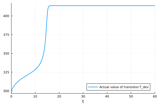
plt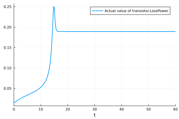
Related
Examples
Experiments
Analyses