Operational Transconductance Amplifier (OTA)
Introduction
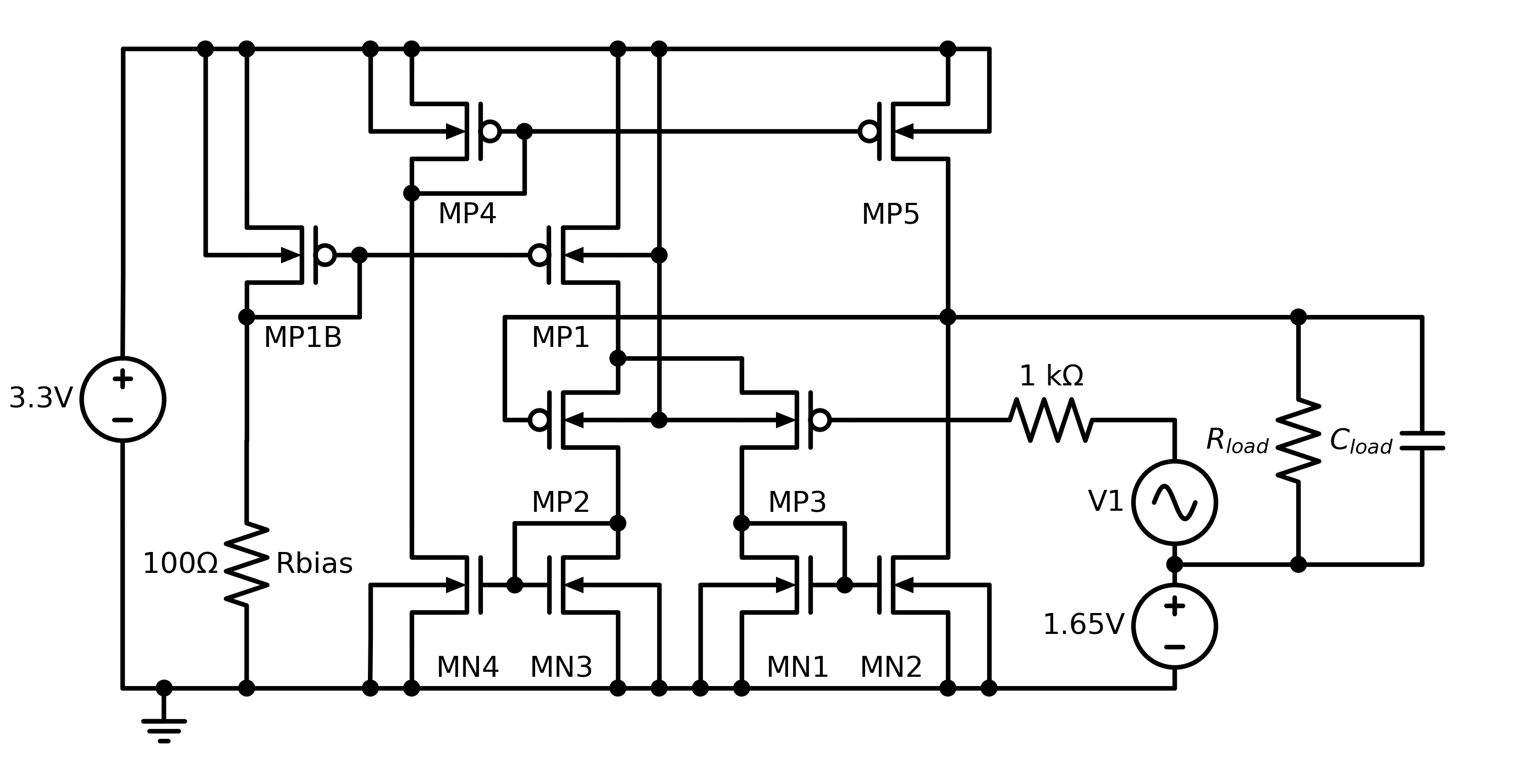
An operational transconductance amplifier (OTA) operates as a voltage-controlled current source. A differential input stage amplifies the voltage difference between its inputs, and the result is available as a current at the output. By varying the output impedance of the load, it's possible to control the amount of saturation seen by the amplifier.
The two-stage design (and device test harness) seen here come from the FAC'14 benchmark suite.
Files
Analyses
DC
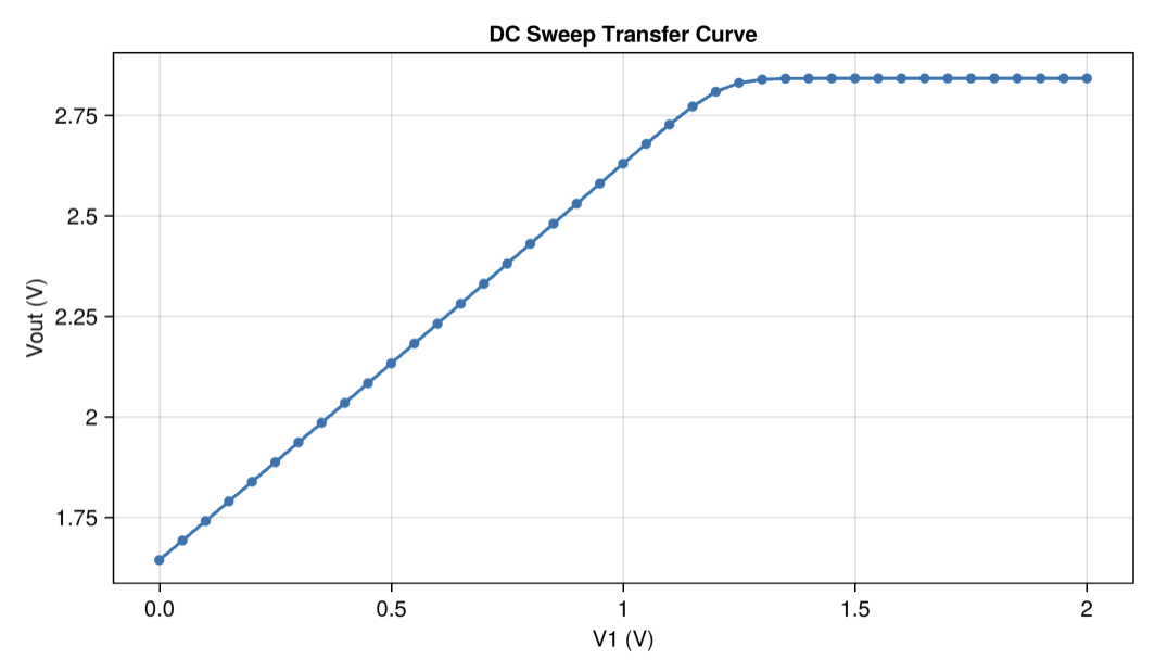
This example runs a DC sweep and shows that the output saturates at sufficiently high input voltages.
API Reference
- Configuring Parameters
- Adding Checks
- Simulating