Butterworth third-order lowpass filter
Introduction
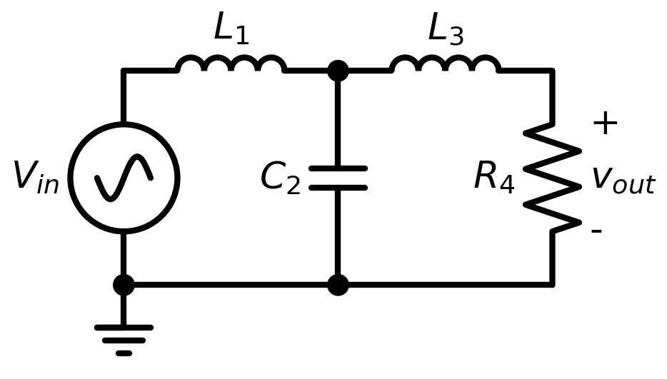
This circuit demonstrates a Butterworth filter of third order, implemented with two inductors, a capacitor and a resistor. The default parameter values are designed to give a cutoff frequency of 10 MHz, however with experimentation different cutoff frequencies and step responses are achievable.
In this circuit the input is a sinusoidal voltage source (with adjustable frequency) and the output is the filtered output, as shown in the attached circuit diagram.
The circuit netlist is contained within the butterworth.spice file in this directory. To begin running the simulation harness, open the butterworth_transient.jl or butterworth_ac.jl files and begin running statements.
Files
butterworth.spice- circuit netlistbutterworth_ac.jl- AC simulation harnessbutterworth_noise.jl- AC noise simulation harnessbutterworth_transient.jl- transient simulation harness
Analyses
Transient
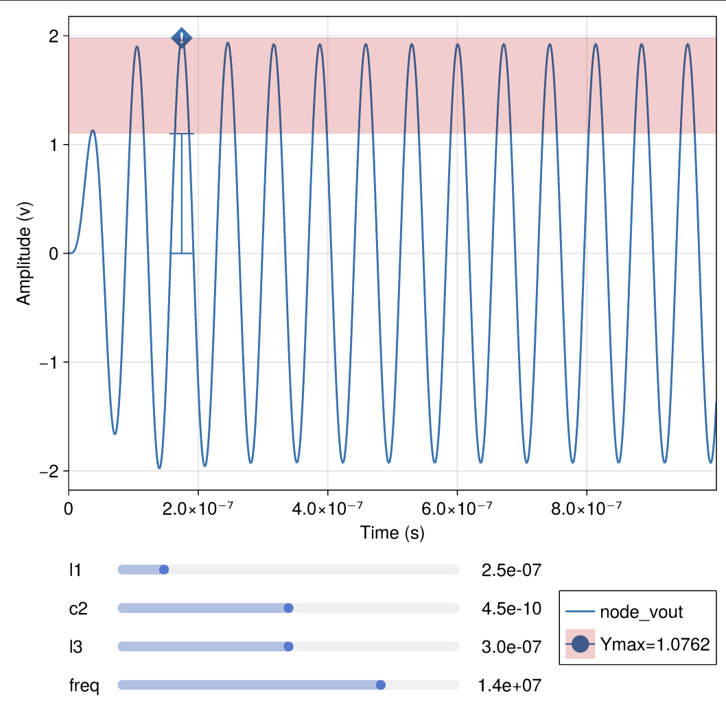
Note that here we have a single measure applied (just as in the example) disallowing the voltage to ever peak above the absolute maximum value above 1.1.
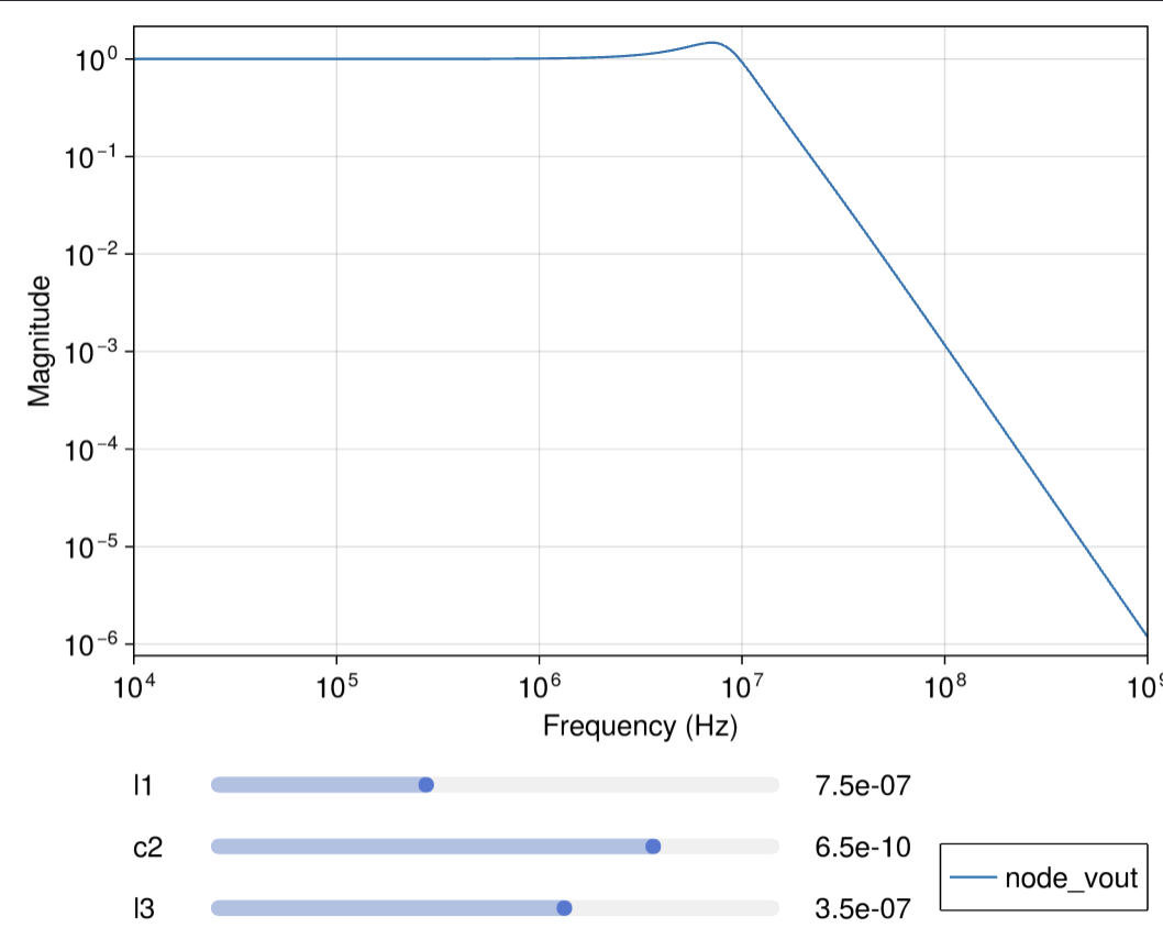
AC
The AC response is calculated for a frequency sweep from 10 kHz to 1 GHz. By moving the sliders the influence of each parametere can be understood. L1 is the primary component for controlling the passband ripple.
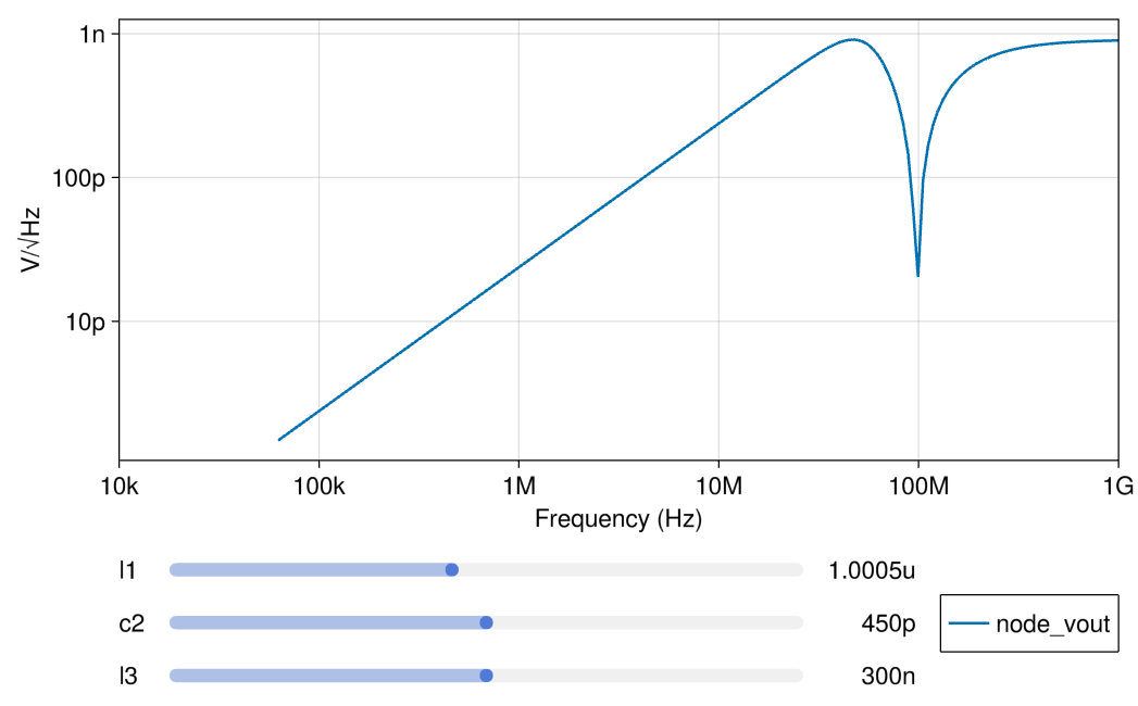
Noise
The Noise spectrum is calculated for a frequency from 10 kHz to 1 Ghz. By moving the sliders the influence of each parametere can be understood.
API Reference
- Configuring Parameters
- Adding Checks
- Simulating
- Inspecting Results