Biased Amplifier
Introduction
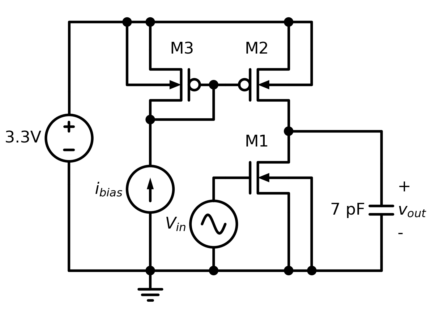
This circuit demonstrates a simple 3-transistor biased amplifier circuit.
The schematic is shown above, for most of this example we will concern ourselves primarily with the behavior of the vout net. This amplifier is sensitive to the bias current, and so we will investigate the sensitivity of vout to the value of the bias_current parameter, which parameterizes the current flowing through ibias.
Files
amplifier_sensitivity.jl- simulation harnessamplifier.spice- circuit netlist
Analyses
Transient
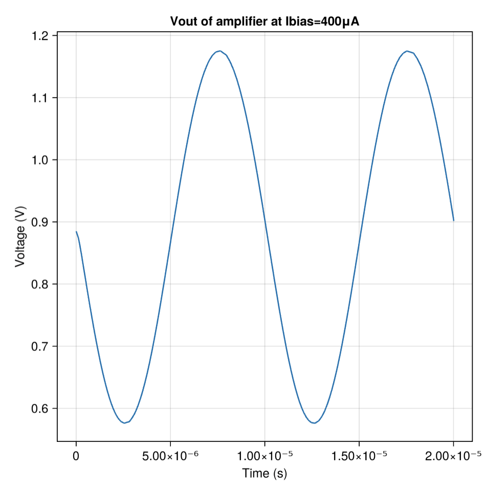
The first result plotted in the example is the voltage of the vout net when ibias is set to 400μA. Because the design is driven by a sinusoidal voltage source on vin, the output is merely a scaled version of that sinusoid, with some added minor nonlinearities that are not easily visible at this scale.
Sensitivity
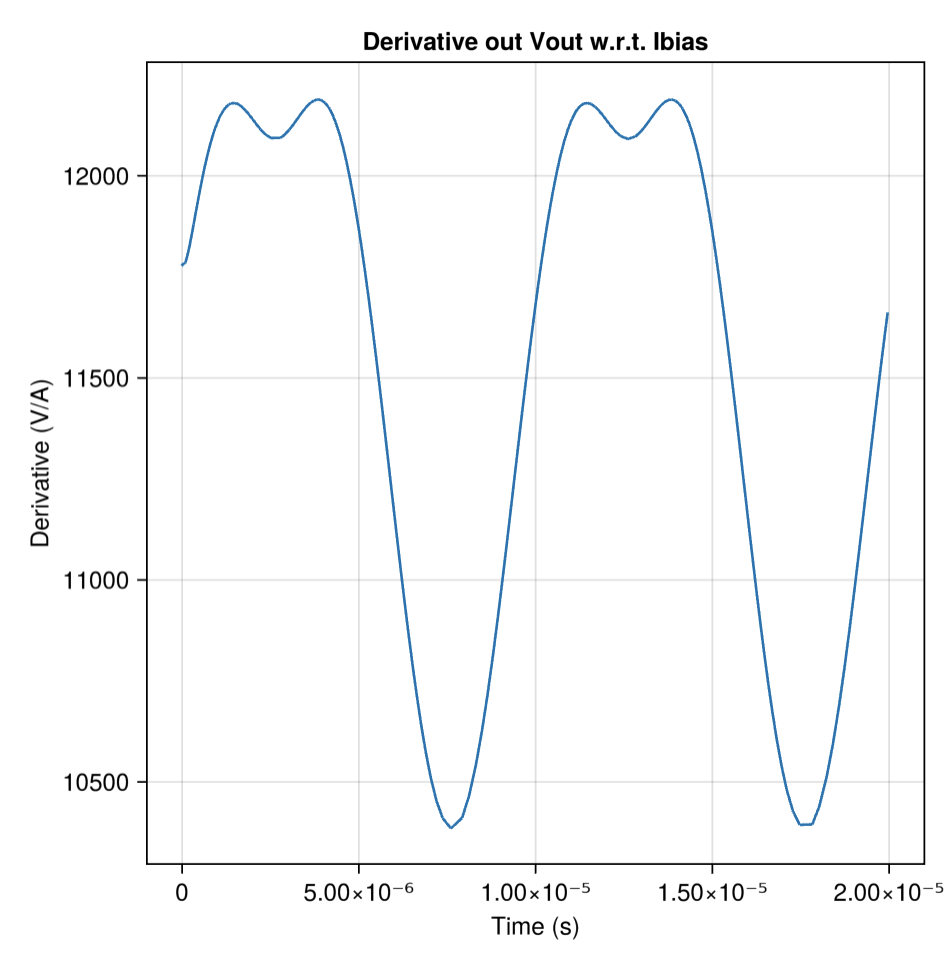
The example then goes on to show the sensitivity (e.g. the derivative) of node_vout with respect to the bias current. This is one of the values that is calculated via sensitivities!(), accessible as an array of solutions (one for each parameter sweep point), then broken out by which parameter the sensitivity is based on, then the output to calculate the sensitivity of. In the example, this sums together as inspecting the value of ssols[1].sensitivities.bias_current.node_vout.
Finally, we verify that our derivative is reasonable by using the derivative to predict what vout would look like at bias_current = 410μA, then actually simulating it and plotting all three signals in one plot:
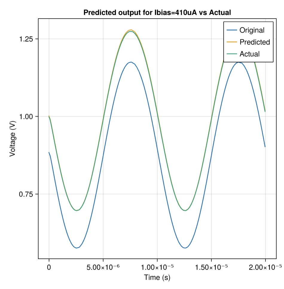
As can be seen, the predicted values are fairly accurate.
API Reference
- Configuring Parameters
- Simulating