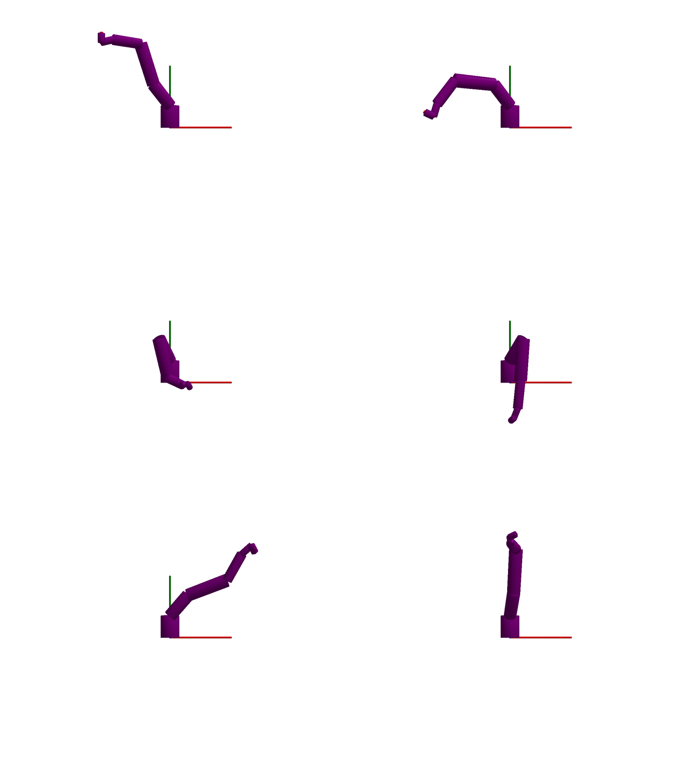
Industrial robot

using Multibody
using ModelingToolkit
using Plots
using JuliaSimCompiler
using OrdinaryDiffEq
using Test

t = Multibody.t
D = Differential(t)
@named robot = Multibody.Robot6DOF()
robot = complete(robot)

length(equations(robot))2253The robot is a medium sized system with some 2000 equations before simplification.
After simplification, the following states are chosen:
ssys = structural_simplify(multibody(robot))
unknowns(ssys)
36-element Vector{JuliaSimCompiler.ADT.IRElement}:
axis3₊motor₊Jmotor₊phi
axis3₊motor₊La₊i
axis2₊motor₊Jmotor₊phi
axis2₊motor₊La₊i
axis1₊motor₊Jmotor₊phi
axis1₊motor₊La₊i
axis3₊controller₊PI₊int₊x
axis3₊motor₊C₊v
axis2₊controller₊PI₊int₊x
axis2₊motor₊C₊v
⋮
axis3₊motor₊Jmotor₊w
axis2₊motor₊Jmotor₊w
axis1₊motor₊Jmotor₊w
mechanics₊r6₊w
mechanics₊r5₊w
mechanics₊r4₊w
mechanics₊r3₊w
mechanics₊r2₊w
mechanics₊r1₊wprob = ODEProblem(ssys, Dict([
robot.mechanics.r1.phi => deg2rad(-60)
robot.mechanics.r2.phi => deg2rad(20)
robot.mechanics.r3.phi => deg2rad(90)
robot.mechanics.r4.phi => deg2rad(0)
robot.mechanics.r5.phi => deg2rad(-110)
robot.mechanics.r6.phi => deg2rad(0)
robot.axis1.motor.Jmotor.phi => deg2rad(-60) * -105 # Multiply by gear ratio
robot.axis2.motor.Jmotor.phi => deg2rad(20) * 210
robot.axis3.motor.Jmotor.phi => deg2rad(90) * 60
]), (0.0, 2.0))
sol = solve(prob, Rodas5P(autodiff=false));
@test SciMLBase.successful_retcode(sol)
plot(sol, idxs = [
robot.pathPlanning.controlBus.axisControlBus1.angle_ref
robot.pathPlanning.controlBus.axisControlBus2.angle_ref
robot.pathPlanning.controlBus.axisControlBus3.angle_ref
robot.pathPlanning.controlBus.axisControlBus4.angle_ref
robot.pathPlanning.controlBus.axisControlBus5.angle_ref
robot.pathPlanning.controlBus.axisControlBus6.angle_ref
], layout=(4,3), size=(800,800), l=(:black, :dash), legend=:outertop, legendfontsize=6)
plot!(sol, idxs = [
robot.pathPlanning.controlBus.axisControlBus1.angle
robot.pathPlanning.controlBus.axisControlBus2.angle
robot.pathPlanning.controlBus.axisControlBus3.angle
robot.pathPlanning.controlBus.axisControlBus4.angle
robot.pathPlanning.controlBus.axisControlBus5.angle
robot.pathPlanning.controlBus.axisControlBus6.angle
], sp=1:6)
plot!(sol, idxs = [
robot.axis1.controller.feedback1.output.u
robot.axis2.controller.feedback1.output.u
robot.axis3.controller.feedback1.output.u
robot.axis4.controller.feedback1.output.u
robot.axis5.controller.feedback1.output.u
robot.axis6.controller.feedback1.output.u
], sp=7:12, lab="Position error", link=:x)
plot!(xlabel=[fill("", 1, 9) fill("Time [s]", 1, 3)])We see that after an initial transient, the robot controller converges to tracking the reference trajectory well. However, since the first three axes of the robot are modeled as slightly flexible, and we are ultimately interested in the tracking performance after the gear box and any flexibilities it may suffer from, we plot also this tracking error
plot(sol, idxs = [
    robot.axis1.controller.feedback1.output.u / ( -105)
    robot.axis2.controller.feedback1.output.u / (210)
    robot.axis3.controller.feedback1.output.u / (60)
], layout=(1,3), lab="Position error, motor side", link=:x)
plot!(sol, idxs = [
            robot.pathPlanning.controlBus.axisControlBus1.angle_ref - robot.mechanics.r1.phi #
            robot.pathPlanning.controlBus.axisControlBus2.angle_ref - robot.mechanics.r2.phi #
            robot.pathPlanning.controlBus.axisControlBus3.angle_ref - robot.mechanics.r3.phi #
], lab="Position error, arm side")
Trajectory planning
In the example, the robot is tracking a reference trajectory generated using the function point_to_point and interfaced from the component KinematicPTP. We can inspect the generated trajectory by plotting the positions, velocities and accelerations (we show one joint only to keep the plot size limited):
plot(sol, idxs = [
            robot.pathPlanning.controlBus.axisControlBus1.angle_ref
            robot.pathPlanning.controlBus.axisControlBus1.speed_ref
            robot.pathPlanning.controlBus.axisControlBus1.acceleration_ref
], layout=(3,1), lab=["\$q\$" "\$\\dot q\$" "\$\\ddot q\$"], xlabel=["" "" "Time [s]"])
3D animation
Multibody.jl supports automatic 3D rendering of mechanisms, we use this feature to illustrate the result of the simulation below:
import GLMakie
Multibody.render(robot, sol; y=2, lookat=[0,1,0], filename = "robot.gif")
[ Info: Loading shape mesh /home/runner/work/Multibody.jl/Multibody.jl/src/robot/../../examples/resources/b0.stl
[ Info: Loading shape mesh /home/runner/work/Multibody.jl/Multibody.jl/src/robot/../../examples/resources/b1.stl
[ Info: Loading shape mesh /home/runner/work/Multibody.jl/Multibody.jl/src/robot/../../examples/resources/b2.stl
[ Info: Loading shape mesh /home/runner/work/Multibody.jl/Multibody.jl/src/robot/../../examples/resources/b3.stl
[ Info: Loading shape mesh /home/runner/work/Multibody.jl/Multibody.jl/src/robot/../../examples/resources/b4.stl
[ Info: Loading shape mesh /home/runner/work/Multibody.jl/Multibody.jl/src/robot/../../examples/resources/b5.stl
[ Info: Loading shape mesh /home/runner/work/Multibody.jl/Multibody.jl/src/robot/../../examples/resources/b6.stl
Kinematics
The coordinates of any point on the mechanism may be obtained in the world coordinate frame by either
output = collect(robot.mechanics.b6.frame_b.r_0)
fkine = JuliaSimCompiler.build_explicit_observed_function(ssys, output)
fkine(prob.u0, prob.p, 0)
3-element Vector{Float64}:
-0.986525726789405
1.3512404737372552
0.5695708939243542Query the solution object with the desired output, e.g.,
sol(0, idxs=output)3-element Vector{Float64}:
-0.986525726789405
1.3512404737372552
0.5695708939243542query the problem with the output, in which case the initial condition is used to compute the output
prob[output]3-element Vector{Float64}:
-0.986525726789405
1.3512404737372552
0.5695708939243542or by building an explicit function (state, parameters, time) -> output
fkine = JuliaSimCompiler.build_explicit_observed_function(ssys, output)
fkine(prob.u0, prob.p, 0)
3-element Vector{Float64}:
-0.986525726789405
1.3512404737372552
0.5695708939243542The function fkine above takes the full state of the robot model, as opposed to only the joint angles.